john deere 111 moo111s242340 wiring diagram manual
This manual provides a comprehensive guide to understanding and repairing the electrical systems of the John Deere 111 tractor. Detailed wiring diagrams and circuit layouts are included to help users diagnose and fix issues efficiently. Essential for technicians and DIY enthusiasts, this resource ensures safe and effective electrical system maintenance.
Overview of the Manual
The John Deere 111 wiring diagram manual is a comprehensive resource designed to guide users through the electrical systems of their tractor. It includes detailed wiring diagrams, circuit layouts, and step-by-step instructions for diagnosing and repairing electrical issues. The manual covers key systems such as ignition, starting, charging, and power take-off (PTO) circuits, ensuring a thorough understanding of the tractor’s electrical components; Whether you’re a professional technician or a DIY enthusiast, this manual provides the essential information needed to perform efficient and accurate repairs. It also emphasizes safety practices and preventive maintenance to keep your tractor running smoothly.
Importance of Wiring Diagrams for Repair and Maintenance
Wiring diagrams are crucial for effective repair and maintenance of the John Deere 111 tractor. They provide a clear visual representation of the electrical system, allowing users to identify components, trace circuits, and diagnose faults accurately. Without a wiring diagram, locating and resolving electrical issues can be challenging and time-consuming. These diagrams also help prevent costly damages by ensuring repairs are done correctly. By following the wiring diagram, users can safely and efficiently troubleshoot problems, replace faulty parts, and maintain optimal tractor performance. This resource is indispensable for both novice and experienced operators, enhancing their ability to keep the tractor operational and reliable.
Understanding the Wiring Diagram
The wiring diagram provides a detailed visual representation of the tractor’s electrical system, enabling users to identify components, trace circuits, and perform repairs efficiently.
Key Components of the John Deere 111 Wiring Diagram
The wiring diagram for the John Deere 111 includes essential components such as the ignition switch, starter solenoid, and alternator. It also outlines the PTO (Power Take-Off) circuit, which controls auxiliary equipment; The diagram highlights the battery, fuses, and circuit breakers that protect the electrical system from overloads. Additionally, it details the wiring connections for the tractor’s lights, gauges, and safety systems. Color-coded lines and symbols help users identify and trace specific circuits, making it easier to diagnose and repair electrical issues. Understanding these components is crucial for maintaining the tractor’s performance and ensuring safe operation.
How to Read and Interpret the Diagram
To effectively use the John Deere 111 wiring diagram, start by identifying the symbols and color codes, which are standardized for clarity. Trace each circuit systematically, beginning from the power source, such as the battery, and follow the flow through fuses, relays, and switches. Pay attention to connectors and ground points, as they are critical for proper electrical function. Use the legend provided in the manual to decode symbols and understand the purpose of each wire. Cross-reference the diagram with the tractor’s physical components to locate and diagnose issues. This methodical approach ensures accurate troubleshooting and repairs, making the diagram an indispensable tool for maintaining the tractor’s electrical system.
Major Electrical Systems in the John Deere 111
The John Deere 111 features key electrical systems, including the ignition, starting circuit, charging system, and power take-off (PTO) connections, all essential for tractor operation and functionality.
Ignition System Wiring
The ignition system wiring in the John Deere 111 is crucial for engine startup and operation. It involves a 6-position ignition switch, connecting to the ignition coil, spark plug, and optional accessories. The wiring diagram shows the circuit breaker inline with ignition wires, ensuring safety and proper current flow. Proper connection of the ignition switch’s terminals is essential for functions like start, run, and accessory modes. Users should refer to the wiring diagram to trace connections accurately, as variations exist between models. Regular inspection of wires and connections prevents issues like spark loss during operation, ensuring reliable engine performance and longevity. Always follow safety guidelines when handling electrical components to avoid risks.
Starting System Circuit
The starting system circuit of the John Deere 111 is designed to initiate engine startup safely and efficiently. It consists of the battery, ignition switch, starter solenoid, and starter motor. The thick red cable connects the battery’s positive terminal to the starter solenoid, which acts as a relay to engage the starter motor. The ignition switch controls the flow of current to the solenoid, activating the starting process. A circuit breaker protects the system from overcurrent conditions. Proper wiring connections are critical to ensure reliable starts and prevent electrical failures. Always consult the wiring diagram for accurate troubleshooting and repairs, adhering to safety guidelines when working with high-current circuits.
Charging System Configuration
The charging system of the John Deere 111 is essential for maintaining battery charge and powering electrical components while the engine runs. It primarily consists of the alternator, voltage regulator, and associated wiring. The alternator is belt-driven by the engine and generates electricity to recharge the battery and supply power to the tractor’s electrical systems. The voltage regulator ensures stable output to prevent overcharging or undercharging. The wiring diagram illustrates connections between the alternator, regulator, battery, and ignition switch. Proper configuration is critical for reliable operation, and any issues can be diagnosed using the wiring diagram to trace electrical flow and identify faults in the charging circuit.
Power Take-Off (PTO) Electrical Connections
The Power Take-Off (PTO) system on the John Deere 111 is designed to activate and control auxiliary equipment such as mowers or snow blowers. The electrical connections for the PTO are detailed in the wiring diagram, showing how the PTO switch integrates with the tractor’s electrical circuit. The PTO switch is typically connected to the ignition circuit, ensuring the system only operates when the engine is running. Fuses and relays protect the PTO circuit from overloads, while the wiring diagram helps trace connections for troubleshooting. Proper setup is crucial for safe and efficient operation of PTO-driven attachments, as incorrect wiring can lead to malfunction or electrical hazards.

Troubleshooting Common Electrical Issues
Common electrical issues on the John Deere 111 often involve faulty connections, blown fuses, or malfunctioning switches. The wiring diagram aids in identifying and isolating problems efficiently.
Diagnosing Faults Using the Wiring Diagram
The wiring diagram is a critical tool for diagnosing electrical faults in the John Deere 111. By tracing circuits and identifying components, users can pinpoint issues like open circuits or short circuits. Color-coded wires and detailed schematics simplify troubleshooting. Common problems include faulty ignition switches, blown fuses, or malfunctioning solenoids. The diagram helps users verify connections and test voltage at key points. For example, if the PTO switch causes spark loss, the diagram can reveal wiring misconnections. Advanced users can use the diagram to identify missing components, such as circuit breakers, which may not be physically present despite being shown in the manual. Regular inspections and preventive maintenance are essential to avoid recurring issues.
Common Problems and Their Solutions
Owners of the John Deere 111 often encounter issues like intermittent starting, faulty PTO engagement, and dimming lights. These problems frequently stem from worn or corroded connectors, loose wires, or blown fuses. Another common issue is spark loss when activating the PTO switch, which can be traced to incorrect wiring configurations. Solutions involve cleaning connections, replacing damaged wires, and ensuring all circuits are properly grounded. Upgrading to heavier-duty fuses or circuit breakers may also resolve recurring electrical failures. Regular inspections of the ignition system and battery connections can prevent these problems from arising. Always refer to the wiring diagram to identify and address issues effectively.
Safety Precautions and Best Practices
Always disconnect the battery before starting repairs to prevent electrical shocks. Wear protective gear like gloves and goggles. Use a multimeter to test live circuits safely. Ensure proper grounding and avoid overloaded circuits to prevent damage or injury.
Safe Handling of Electrical Components
Safely handling electrical components is crucial to avoid damage and injury. Always disconnect the battery before starting any repairs to eliminate power sources. Use a multimeter to test for voltage, ensuring no live currents are present. Wear insulated gloves and safety goggles to protect against electrical shocks. Avoid touching wiring or components with wet hands or while standing on conductive surfaces. Properly secure loose wires to prevent accidental short circuits. Label disconnected wires to ensure correct reconnection. Grounding tools and equipment reduces static discharge risks. Follow the wiring diagram to identify circuits accurately, and never bypass safety devices like fuses or circuit breakers.
Preventive Maintenance Tips
Regular inspections of the wiring and electrical systems are essential to prevent failures. Clean connectors and terminals to ensure proper connections and avoid corrosion. Check wires for signs of wear, fraying, or damage, and replace them promptly. Store the tractor in a dry, cool place to protect electrical components from moisture and temperature extremes. Use a multimeter to test circuit continuity and voltage levels periodically. Keep the wiring diagram handy for quick reference during inspections. Replace fuses and circuit breakers as needed, and avoid using makeshift repairs. Schedule annual professional maintenance to ensure optimal performance and safety of the electrical systems.
Tools and Materials Needed for Repairs
A multimeter, wire strippers, and insulated screwdrivers are essential tools for diagnosing and repairing electrical systems. High-quality wires, connectors, and electrical tape are recommended for durable repairs.
Essential Tools for Electrical Repairs
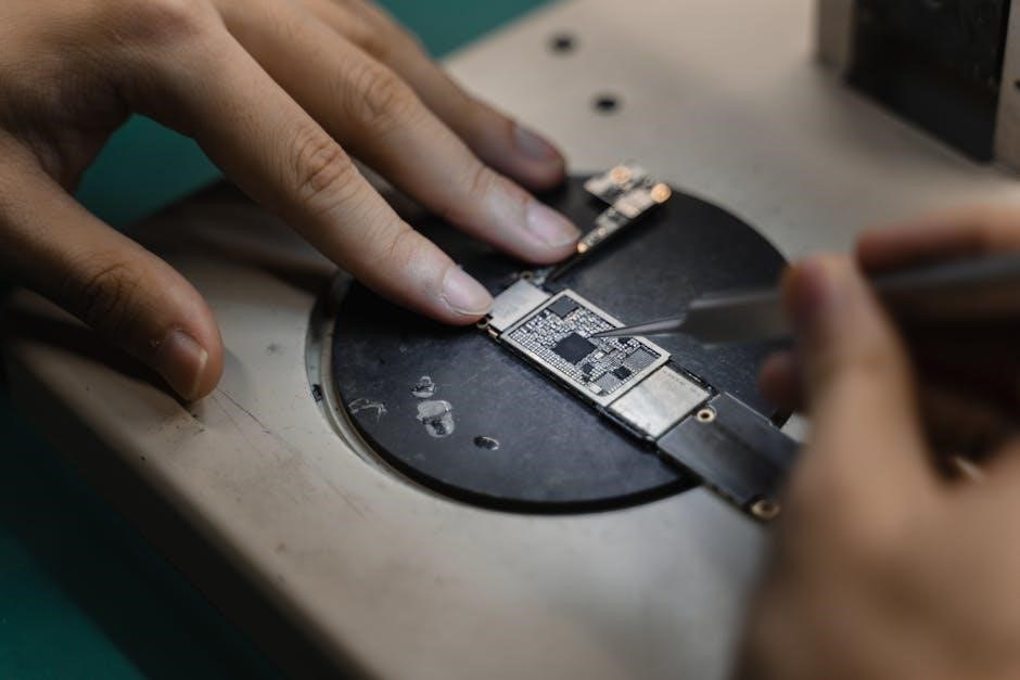
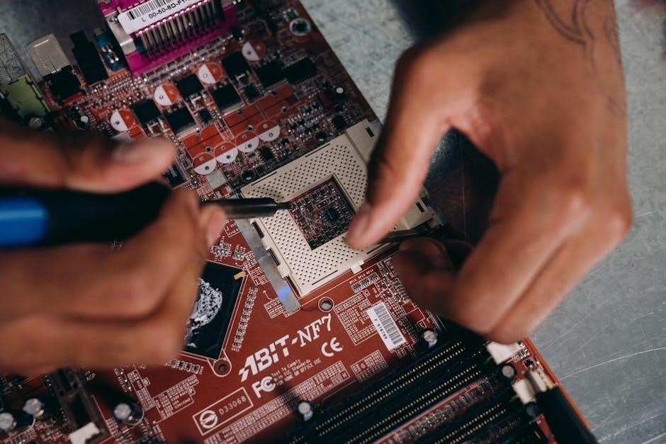
For effective electrical repairs, gather essential tools like a multimeter, wire strippers, and insulated screwdrivers. A wiring diagram manual is crucial for identifying circuits. Pliers, crimping tools, and a soldering iron are also necessary for secure connections. Ensure you have high-quality wires, connectors, and electrical tape for reliable fixes. A circuit tester can help verify live wires, while a fuse puller safely removes fuses. Personal protective equipment, such as gloves and safety glasses, is vital for protection. Having these tools organized and within reach streamlines the repair process, ensuring accuracy and efficiency when working with the John Deere 111’s electrical systems.
Recommended Materials for Wiring Repairs
For reliable wiring repairs, use high-quality materials like durable, heat-resistant wiring harnesses and insulated connectors. Heavy-duty electrical tape, shrink tubing, and dielectric grease are essential for sealing and protecting connections. Ensure all components meet OEM standards for compatibility and longevity. Replace faulty fuses and relays with genuine or equivalent parts to maintain system integrity. Use waterproof connectors and seals to prevent corrosion, especially in harsh outdoor conditions. Keep spare terminals, wiring nuts, and crimp connectors on hand for quick fixes. Proper materials ensure safe and efficient electrical system performance, aligning with the specifications outlined in the John Deere 111 wiring diagram manual.
Step-by-Step Repair Guide
Use the wiring diagram to identify and repair electrical faults step-by-step. Disconnect battery, test circuits, and replace faulty components using appropriate tools for safe and effective fixes.
Replacing Faulty Wires and Connectors
Begin by disconnecting the battery to ensure safety. Use the wiring diagram to locate the faulty wire or connector. Test for continuity using a multimeter to confirm the issue. Carefully remove the damaged wire, taking note of its routing and connections. Install the new wire, ensuring it matches the gauge and color coding specified in the manual. Securely attach connectors, verifying proper alignment and tightness. Finally, reconnect the battery and test the system to confirm the repair. Always wear protective gear and follow safety guidelines when handling electrical components;
Upgrading Electrical Components
Upgrading electrical components in your John Deere 111 tractor can enhance performance and reliability. Always refer to the wiring diagram to identify compatible parts and ensure proper installation. Start by disconnecting the battery to avoid accidental power surges. Use high-quality replacement wires and connectors that match the original specifications. For advanced upgrades, such as adding LED lights or auxiliary power outlets, follow the manufacturer’s instructions and verify compatibility with your tractor’s electrical system. After installation, test all circuits to ensure functionality. Keep detailed records of upgrades for future reference and maintenance. Regularly inspect upgraded components to prevent potential failures and maintain optimal performance.
Advanced Topics in Wiring Diagrams
Advanced wiring diagram topics include interpreting complex circuits, understanding fuse configurations, and diagnosing intricate electrical issues. These skills enhance troubleshooting and customization of the John Deere 111 tractor.
Understanding Fuse and Circuit Breaker Configurations
Fuse and circuit breaker configurations are crucial for protecting the John Deere 111’s electrical systems. Fuses act as sacrificial devices, interrupting current during overloads to prevent damage. Circuit breakers perform a similar function but can be reset after tripping. The wiring diagram identifies fuse locations and ratings, ensuring correct replacement. Understanding these configurations helps in diagnosing issues like intermittent power loss or complete system shutdowns. Proper maintenance involves checking fuses and breakers regularly to ensure optimal performance and safety. This knowledge is essential for both routine inspections and complex electrical repairs, making it a cornerstone of effective tractor maintenance.
Advanced Diagnostics for Complex Electrical Issues
Advanced diagnostics for complex electrical issues in the John Deere 111 involve using specialized tools and techniques to identify and resolve deep-rooted problems. A multimeter is essential for testing voltage, resistance, and continuity in circuits. Scan tools can help identify fault codes in modern electronic systems. For intermittent issues, thermal imaging can detect heat-related faults. The wiring diagram is crucial for tracing circuits and pinpointing faulty components. Advanced diagnostics also involve testing relays, solenoids, and electronic control modules. By systematically isolating and testing each component, technicians can diagnose issues like erratic sensor readings or communication errors between modules. This approach ensures efficient resolution of even the most stubborn electrical problems.
Maintenance and Upkeep of Electrical Systems
Regular inspections of wiring, connectors, and fuses prevent electrical failures. Clean corrosion from terminals and replace worn-out components promptly to ensure reliable tractor operation and longevity.
Regular Inspections to Prevent Failures

Regular inspections are crucial to identify potential electrical issues before they lead to system failures. Start by examining the wiring harness for signs of wear, corrosion, or damage. Check all connectors and terminals for tightness and cleanliness. Inspect fuses and circuit breakers to ensure they are functioning properly and replace any blown fuses promptly; Use the wiring diagram to trace circuits and verify connections. Look for frayed wires, loose connections, or exposed conductors that could cause short circuits. Test the ignition switch and PTO switch for proper operation. Schedule inspections seasonally or every 50 hours of use to maintain reliability and prevent unexpected breakdowns.
Scheduled Maintenance for Optimal Performance
Regular maintenance is essential to ensure the electrical systems of your John Deere 111 operate efficiently. Start by checking the battery terminals for corrosion and tightness. Inspect the ignition system, including the spark plug wires and ignition coil, for wear or damage. Replace the air filter and ensure all electrical connections are clean and secure. Check the fuse box and circuit breakers, replacing any blown fuses or tripped breakers. Lubricate switches and connectors to prevent corrosion. Schedule these checks seasonally or every 50 hours of operation to maintain reliability and avoid costly repairs. Refer to the wiring diagram for specific components and procedures.
The John Deere 111 wiring diagram manual is an invaluable resource for troubleshooting, maintenance, and repairs. It empowers users to diagnose and resolve electrical issues confidently, ensuring optimal performance and longevity of their tractor. By following the guidelines and understanding the wiring systems, operators can maintain their equipment effectively. This manual serves as a comprehensive guide, encouraging further exploration and mastery of electrical diagnostics for enhanced productivity and reliability.
The John Deere 111 wiring diagram manual is a detailed guide for understanding and repairing electrical systems. It includes wiring layouts, circuit diagrams, and troubleshooting steps. Key components such as the ignition system, starting circuit, and PTO connections are covered. The manual emphasizes safety practices and preventive maintenance to ensure optimal tractor performance. By providing clear instructions and diagrams, it empowers users to diagnose faults and replace components effectively. Regular inspections and scheduled maintenance are highlighted as essential for preventing failures. This resource is invaluable for technicians and DIY enthusiasts, offering a comprehensive approach to electrical system care and repair.
Encouragement for Further Learning and Exploration
Mastery of the John Deere 111 wiring diagram manual is just the beginning of your journey in understanding tractor electrical systems. Encourage yourself to explore beyond the manual by practicing repairs and experimenting with new diagnostic techniques. Join online forums and communities to share insights and learn from experienced technicians. The more you engage with these systems, the more confident you’ll become in tackling complex electrical challenges. Remember, continuous learning enhances problem-solving skills and deepens your understanding of tractor mechanics. Embrace curiosity and keep exploring—every wiring diagram tells a story of how your tractor operates, and understanding it fully will empower you to keep your equipment running at its best.